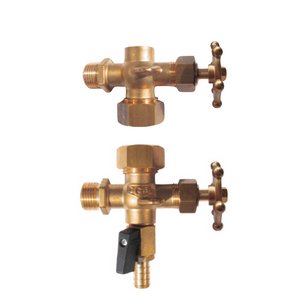
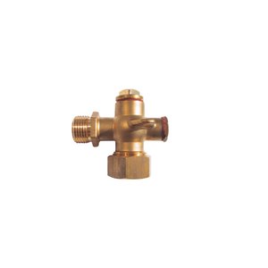
Water level valves
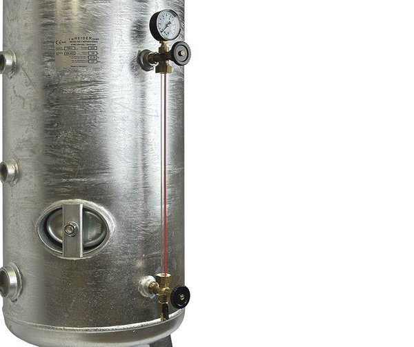
Brass water level indicators
with oil-resistant seals
Connection to vessel: ½"
Connection top side: ¼" for pressure gauge
delivered in pairs (top and bottom)
optionally with brass handwheel or bakelite handwheel
optionally with drain valve or plug
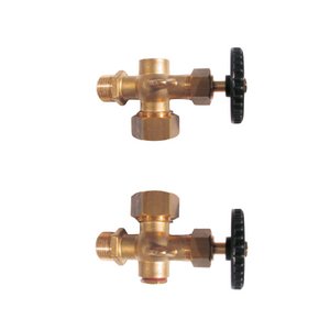
Water level gauge
No. 1aa
|
Handwheel
|
bakelite
|
|
Upper part
|
1/4" for pressure gauge
|
|
Lower part
|
plug
|
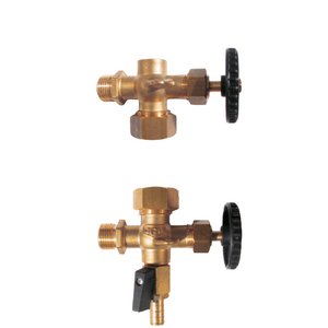
Water level gauge
No. 1ab
|
Handwheel
|
bakelite
|
|
Upper part
|
1/4" for pressure gauge
|
|
Lower part
|
drain valve
|
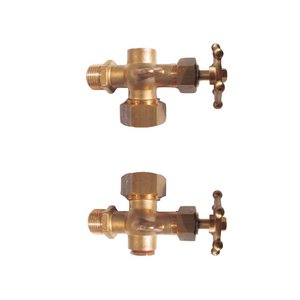
Water level gauge
No. 1ac
|
Handwheel
|
brass
|
|
Upper part
|
1/4" for pressure gauge
|
|
Lower part
|
plug
|
Water level gauge
No. 1ad
|
Handwheel
|
brass
|
|
Upper part
|
1/4" for pressure gauge
|
|
Lower part
|
drain valve
|
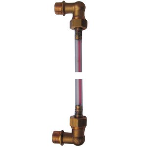
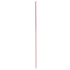
Water level tube
XTR
|
secure installation without sleeves
|
|
quickly adjustable
|
|
with red reflective stripes
|
|
Lengths: 500 - 1.600 mm
|
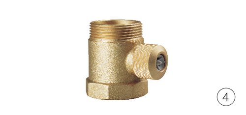
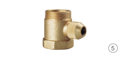
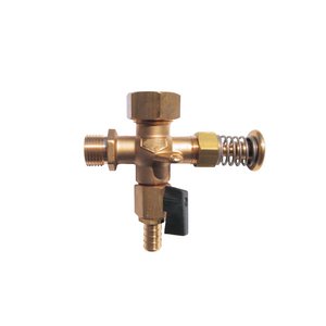
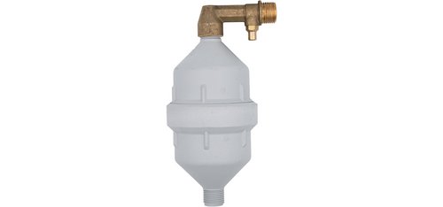
Aerator for centrifugal pumps for automatic filling
of the air cushion in galvanised pressure vessels.
Max. operating pressure: 10 bar
Available in two dimensions:
Pressure vessels to 500 l - connection: ½" x ½"
Pressure vessels to 2.000 l - connection: ½" x ¾"
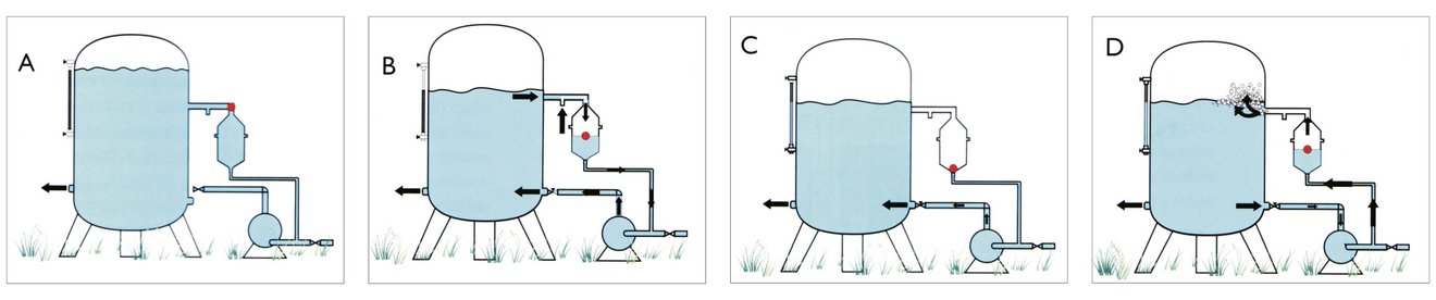
A - The centrifugal pump stops. The vessel is full of water.
B - When the centrifugal pump starts, negative pressure is generated and the water is sucked out of the vessel. Air enters through the aerator valve.
C - The aerator fills with air until the ball closes the hole connecting it to the pump.
D - When the centrifugal pump stops, the air in the aerator enters in the pressure vessel due to the principle of communicating vessels and, being lighter, flows upwards into the pressure vessel.
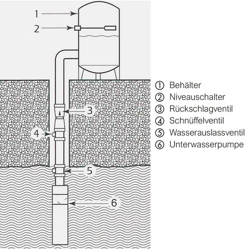
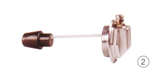
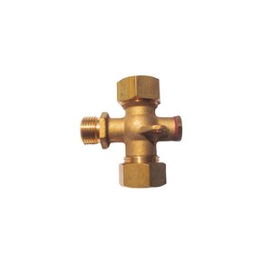
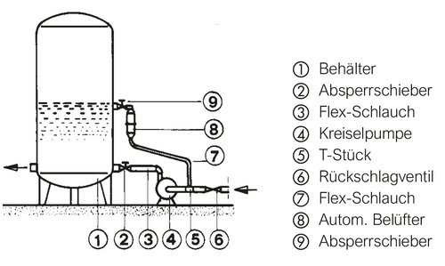
The sniff valve is located below the check valve in the area above the water level
(must be able to draw in air) is installed in the riser pipe and is used for filling
of the air cushion in galvanised pressure vessels when operating a submersible pump.
The submersible pump must not have a ckech valve incorporated,
otherwise, this must be removed or a water outlet valve must be installed in the
water-bearing layer above the pump.
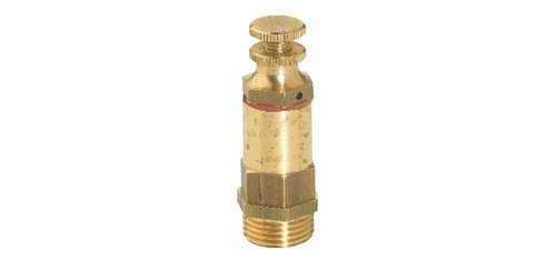
The level switch is installed in the pressure vessel and releases any excess air if necessary.
When the submersible pump switches off, the water flows back into the well either through
the submersible pump or through the water outlet valve. The sniffer valve allows
air to fill the pipe. The air is forced into the pressure tank the next time the pump is started.